Monday, January 26, 2009

DC Parallel Circuit

Resistance in a Parallel Circuit
A parallel circuit is formed when two or more resistances are placed in a circuit side-by-side so that current can flow through more than one path. The illustration shows two resistors placed side-by-side. There are two paths of current flow. One path is from the negative terminal of the battery through R1returning to the positive terminal. The second path is from the negative terminal of the battery through R2 returning to the positive terminal of the battery.


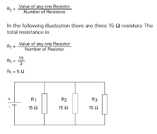
Formula for Equal Value Resistors in a Parallel Circuit
To determine the total resistance when resistors are of equal value in a parallel circuit, use the following formula:


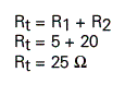
Formula for Unequal Resistors in a Parallel Circuit
There are two formulas to determine total resistance for resistors of any value in a parallel circuit. The first formula is used when there are any number of resistors.


Voltage in a Parallel Circuit When resistors are placed in parallel across a voltage source, the voltage is the same across each resistor. In the following illustration three resistors are placed in parallel across a 12 volt battery. Each resistor has 12 volts available to it.


Current in a Parallel Circuit
Current flowing through a parallel circuit divides and flows through each branch of the circuit.


Total current in a parallel circuit is equal to the sum of the current in each branch. The following formula applies to current in a parallel circuit.
It = I1 + I2 + I3+ In...


Current Flow with Equal Value Resistors in a Parallel Circuit

When equal resistances are placed in a parallel circuit, opposition to current flow is the same in each branch. In the following circuit R1and R2 are of equal value. If total current (It) is 10 amps, then 5 amps would flow through R1and 5 amps would flow through R2.


Current Flow with Unequal Value Resistors in a Parallel Circuit
When unequal value resistors are placed in a parallel circuit, opposition to current flow is not the same in every circuit branch. Current is greater through the path of least resistance. In the following circuit R1is 40 ohms and R2 is 20 ohms. Small values of resistance means less opposition to current flow. More current will flow through R2 than R1.


Total current can also be calculated by first calculating total resistance, then applying the formula for Ohm’s Law.


DC Series Circuit

Resistance in a Series Circuit
A series circuit is formed when any number of resistors are connected end-to-end so that there is only one path for current to flow. The resistors can be actual resistors or other devices that have resistance. The following illustration shows four resistors connected end-to-end. There is one path of current flow from the negative terminal of the battery through R4, R3, R2, R1 returning to the positive terminal.


Formula for Series Resistance The values of resistance add in a series circuit. If a 4 ohms resistor is placed in series with a 6 ohms resistor, the total value will be 10 ohms. This is true when other types of resistive devices are placed in series. The mathematical formula for resistance in series is:

Rt = R1 + R2 + R3 + R4 + R5+ Rn...

In this example, the circuit includes five series resistors.


Current in a Series Circuit The equation for total resistance in a series circuit allows us to simplify a circuit. Using Ohm’s Law, the value of current can be calculated. Current is the same anywhere it is measured in a series circuit.


Voltage in a Series Circuit
Voltage can be measured across each of the resistors in a circuit. The voltage across a resistor is referred to as a voltage drop. A German physicist, Gustav Kirchhoff, formulated a law which states the sum of the voltage drops across the resistances of a closed circuit equals the total voltage applied to the circuit. In the following illustration, four equal value resistors of 1.5 ohms each have been placed in series with a 12 volt battery. Ohm’s Law can be applied to show that each resistor will “drop” an equal amount of voltage.


If voltage were measured across any single resistor, the meter would read three volts. If voltage were read across a combination of R3 and R4 the meter would read six volts. If voltage were read across a combination of R2, R3, and R4 the meter would read nine volts. If the voltage drops of all four resistors were added together the sum would be 12 volts, the original supply voltage of the battery.

Voltage Division in a Series Circuit
It is often desirable to use a voltage potential that is lower than the supply voltage. To do this, a voltage divider, similar to the one illustrated, can be used. The battery represents Ein which in this case is 50 volts. The desired voltage is represented by Eout, which mathematically works out to be 40 volts. To calculate this voltage, first solve for total resistance.


Ohm’s Law

George Simon Ohm and Ohm’s Law The relationship between current, voltage and resistance was studied by the 19th century German mathematician, George Simon Ohm. Ohm formulated a law which states that current varies directly with voltage and inversely with resistance. From this law the following formula is derived:


I = E / R OR CURRENT = VOLTAGE / RESISTANCE


Ohm’s Law is the basic formula used in all electrical circuits. Electrical designers must decide how much voltage is needed for a given load, such as computers, clocks, lamps and motors. Decisions must be made concerning the relationship of current, voltage and resistance. All electrical design and analysis begins with Ohm’s Law. There are three mathematical ways to express Ohm’s Law. Which of the formulas is used depends on what facts are known before starting and what facts need to be known.


I = E / R E = I * R R = E / I


Ohm’s Law Triangle There is an easy way to remember which formula to use. By arranging current, voltage and resistance in a triangle, one can quickly determine the correct formula.


Using the Triangle To use the triangle, cover the value you want to calculate. The remaining letters make up the formula.


Ohm’s Law can only give the correct answer when the correct values are used. Remember the following three rules:

• Current is always expressed in amperes or amps
• Voltage is always expressed in volts
• Resistance is always expressed in ohms

Simple Electric Circuit

An Electric Circuit
A fundamental relationship exists between current, voltage, and resistance. A simple electric circuit consists of a voltage source, some type of load, and a conductor to allow electrons to flow between the voltage source and the load. In the following circuit a battery provides the voltage source, electrical wire is used for the conductor, and a light provides the resistance. An additional component has been added to this circuit, a switch. There must be a complete path for current to flow. If the switch is open, the path is incomplete and the light will not illuminate. Closing the switch completes the path, allowing electrons to leave the negative terminal and flow through the light to the positive terminal.


An Electrical Circuit Schematic
The following schematic is a representation of an electrical circuit, consisting of a battery, a resistor, a voltmeter and an ammeter. The ammeter, connected in series with the circuit, will show how much current flow in the circuit. The voltmeter, connected across the voltage source, will show the value of voltage supplied from the battery. Before an analysis can be made of a circuit, we need to understand Ohm’s Law.


Resistance

A third factor that plays a role in an electrical circuit is resistance. All material impedes the flow of electrical current to some extent. The amount of resistance depends upon composition, length, cross-section and temperature of the resistive material. As a rule of thumb, resistance of a conductor increases with an increase of length or a decrease of cross-section. Resistance is designated by the symbol “R”. The unit of measurement for resistance is ohms (ohms).

Resistance Circuit Symbols Resistance is usually indicated symbolically on an electrical drawing by one of two ways. An unfilled rectangle is commonly used. A zigzag line may also be used.


Resistance can be in the form of various components. A resistor may be placed in the circuit, or the circuit might contain other devices that have resistance.

Units of Measurement
The following chart reflects special prefixes that are commonly used when dealing with values of resistance:

Voltage

Electricity can be compared with water flowing through a pipe. A force is required to get water to flow through a pipe. This force comes from either a water pump or gravity. Voltage is the force that is applied to a conductor that causes electric current to flow.


Electrons are negative and are attracted by positive charges. They will always be attracted from a source having an excess of electrons, thus having a negative charge, to a source having a deficiency of electrons, giving it a positive charge. The force required to make electricity flow through a conductor is called a difference in potential, electromotive force (emf), or voltage. Voltage is designated by the letter “E”, or the letter “V”. The unit of measurement for voltage is volts which is also designated by the letter “V”.


Voltage Sources
An electrical voltage can be generated in various ways. A battery uses an electrochemical process. A car’s alternator and a power plant generator utilize a magnetic induction process. All voltage sources share the characteristic of an excess of electrons at one terminal and a shortage at the other terminal. This results in a difference of potential between the two terminals.


Voltage Circuit Symbol

The terminals of a battery are indicated symbolically on an electrical drawing by two lines. The longer line indicates the positive terminal. The shorter line indicates the negative terminal.


Units of Measurement The following chart reflects special prefixes that are used when dealing with very small or large values of voltage:

Prefix Symbol Decimal
1 kilovolt 1 kV 1000 V
1 millivolt 1 mV 1/1000 V
1 microvolt 1 mV 1/1,000,000 V

Sunday, January 25, 2009

Current

Electricity is the flow of free electrons in a conductor from one atom to the next atom in the same general direction. This flow of electrons is referred to as current and is designated by the symbol “I”. Electrons move through a conductor at different rates and electric current has different values. Current is determined by the number of electrons that pass through a cross-section of a conductor in one second. We must remember that atoms are very small. It takes about 1,000,000,000,000,000,000,000,000 atoms to fill one cubic centimeter of a copper conductor. This number can be simplified using mathematical exponents. Instead of writing 24 zeros after the number 1, write 10 rest to 24. Trying to measure even small values of current would result in unimaginably large numbers. For this reason current is measured in amperes which is abbreviated “amps”. The letter “A” is the symbol for amps. A current of one amp means that in one second about 6.24 x 10 rest to 18 electrons move through a cross-section of conductor. These numbers are given for information only and you do not need to be concerned with them. It is important, however, to understand the concept of current flow.


Units of Measurement
The following chart reflects special prefixes that are used when dealing with very small or large values of current:

Prefix Symbol Decimal

1 kiloampere 1 kA 1000 A
1 milliampere 1 mA 1/1000 A
1 microampere 1 mA 1/1,000,000 A


Direction of Current Flow
Some authorities distinguish between electron flow and current flow. Conventional current flow theory ignores the flow of electrons and states that current flows from positive to negative. To avoid confusion, this book will use the electron flow concept which states that electrons flow from negative to positive.


Electric Charges

Neutral State of an Atom
Elements are often identified by the number of electrons in orbit around the nucleus of the atoms making up the element and by the number of protons in the nucleus. A hydrogen atom, for example, has only one electron and one proton. An aluminum atom (illustrated) has 13 electrons and 13 protons. An atom with an equal number of electrons and protons is said to be electrically neutral.


Positive and Negative Charges
Electrons in the outer band of an atom are easily displaced by the application of some external force. Electrons which are forced out of their orbits can result in a lack of electrons where they leave and an excess of electrons where they come to rest. The lack of electrons is called a positive charge because there are more protons than electrons. The excess of electrons has a negative charge. A positive or negative charge is caused by an absence or excess of electrons. The number of protons remains constant.


Attraction and Repulsion of Electric Charges
The old saying, “opposites attract,” is true when dealing with electric charges. Charged bodies have an invisible electric field around them. When two like-charged bodies are brought together, their electric fields repel one body from the other. When two unlike-charged bodies are brought together, their electric fields attract one body to the other.

The electric field around a charged body forms invisible lines of force. These invisible lines of force cause the attraction or repulsion. Lines of force are shown leaving a body with a positive charge and entering a body with a negative charge.


Coulomb’s Law
During the 18th century a French scientist, Charles A. Coulomb, studied fields of force that surround charged bodies. Coulomb discovered that charged bodies attract or repel each other with a force that is directly proportional to the product of the charges, and inversely proportional to the square of the distance between them. Today we call this Coulomb’s Law of Charges. Simply put, the force of attraction or repulsion depends on the strength of the charges and the distance between them.

Conductors,Insulators and Semiconductors

Conductors An electric current is produced when free electrons move from one atom to the next. Materials that permit many electrons to move freely are called conductors. Copper, silver, aluminum, zinc, brass, and iron are considered good conductors. Copper is the most common material used for conductors and is relatively inexpensive.


Insulators Materials that allow few free electrons are called insulators. Materials such as plastic, rubber, glass, mica, and ceramic are good insulators.


An electric cable is one example of how conductors and insulators are used. Electrons flow along a copper conductor to provide energy to an electric device such as a radio, lamp, or a motor. An insulator around the outside of the copper conductor is provided to keep electrons in the conductor.


Semiconductors Semiconductor materials, such as silicon, can be used to manufacture devices that have characteristics of both conductors and insulators. Many semiconductor devices will act like a conductor when an external force is applied in one direction. When the external force is applied in the opposite direction, the semiconductor device will act like an insulator. This principle is the basis for transistors, diodes, and other solid-state electronic devices.


Electron Theory

Elements of an Atom All matter is composed of molecules which are made up of a combination of atoms. Atoms have a nucleus with electrons orbiting around it. The nucleus is composed of protons and neutrons (not shown). Most atoms have an equal number of electrons and protons. Electrons have a negative charge (-). Protons have a positive charge (+). Neutrons are neutral. The negative charge of the electrons is balanced by the positive charge of the protons. Electrons are bound in their orbit by the attraction of the protons. These are referred to as bound electrons.


Free Electrons Electrons in the outer band can become free of their orbit by the application of some external force such as movement through a magnetic field, friction, or chemical action. These are referred to as free electrons. A free electron leaves a void which can be filled by an electron forced out of orbit from another atom. As free electrons move from one atom to the next an electron flow is produced. This is the basis of electricity.


Introduction

Welcome to the first course in the STEP series, Siemens Technical Education Program designed to understand basics of electricity more effectively. .

Upon completion of Basics of Electricity you will be able to:

• Explain the difference between conductors and insulators

• Use Ohm’s Law to calculate current, voltage, and resistance

• Calculate equivalent resistance for series, parallel, or series-parallel circuits

• Calculate voltage drop across a resistor

• Calculate power given other basic values

• Identify factors that determine the strength and polarity of a current-carrying coil’s magnetic field

• Determine peak, instantaneous, and effective values of an AC sine wave

• Identify factors that effect inductive reactance and capacitive reactance in an AC circuit

• Calculate total impedance of an AC circuit

• Explain the difference between real power and apparent power in an AC circuit

• Calculate primary and secondary voltages of single-phase and three-phase transformers

• Calculate kVA of a transformer

Hit Counter